Ford Escape 2020-2025 Service Manual / Electrical / Information and Entertainment Systems / Information and Entertainment System - General Information / Removal and Installation - Telematics Control Unit (TCU) Module
Ford Escape: Information and Entertainment System - General Information / Removal and Installation - Telematics Control Unit (TCU) Module
Special Tool(s) / General Equipment
| Interior Trim Remover |
Removal
NOTE: Removal steps in this procedure may contain installation details.
-
NOTE: If installing a new module, it is necessary to upload the module configuration information to the scan tool prior to removing the module. This information must be downloaded into the new module after installation.
Using a diagnostic scan tool, begin the PMI process for the TCU following the on-screen instructions.
Vehicles with automatic transmission
-
NOTICE: After releasing the clips and hooks position the assembly forward off the locating dowels then up or damage to the trim plate may occur.
Position the console center top trim panel up for access.
-
Release the clips.
-
Release the retaining hooks and position front
of the assembly up. Position the assembly forward off the rear locating
dowels then up.
-
Release the clips.
.jpg) |
-
Disconnect the connectors and remove the console center top trim panel.
.jpg) |
Vehicles with manual transmission
.jpg) |
All vehicles
-
Remove the screw cover.
Use the General Equipment: Interior Trim Remover
.jpg) |
-
Remove the screw, release the clips and remove the LH console side trim panel.
Use the General Equipment: Interior Trim Remover
.jpg) |
-
Release the clips and remove the RH console side trim panel.
Use the General Equipment: Interior Trim Remover
.jpg) |
-
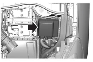
Remove the bolt and disconnect the electrical connectors.
Torque: 22 lb.in (2.5 Nm)
.jpg) |
-
Remove the bolt, disconnect the electrical connectors and remove the TCU and bracket as an assembly.
Torque: 22 lb.in (2.5 Nm)
.jpg) |
-
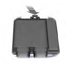
Remove the screws and the TCU .
.jpg) |
Installation
-
To install, reverse the removal procedure.
-
NOTE: This step is only necessary if replacing the TCU .
Using a diagnostic scan tool, complete the PMI process for the TCU following the on-screen instructions.
 Removal and Installation - SYNC Module [APIM] to Universal Serial Bus (USB) Port Cable
Special Tool(s) /
General Equipment
Interior Trim Remover
Removal
SYNC module [APIM] to universal serial bus (USB) hub cable (instrument panel side)
Remove the APIM ...
 Removal and Installation - Telematics Control Unit (TCU) Module Antenna
Removal
NOTE:
Removal steps in this procedure may contain installation details.
Remove the instrument panel upper section.
Refer to: Instrument Panel Upper Section (501-12 Instrument Panel and Console, Removal and Installation)...
Other information:
Ford Escape 2020-2025 Service Manual: Removal and Installation - Fuel Vapor Vent Valve - Plug-In Hybrid Electric Vehicle (PHEV)
Removal WARNING: Do not smoke, carry lighted tobacco or have an open flame of any type when working on or near any fuel-related component. Highly flammable mixtures may be present and may be ignited. Failure to follow these instructions may result in serious personal injury...
Ford Escape 2020-2025 Service Manual: Removal and Installation - Side Obstacle Detection Control Module (SODCM)
Removal Side obstacle detection control module NOTE: This step is only necessary if the SODL or SODR is being replaced. NOTE: This procedure can be used for all locations of the component. Using a diagnostic scan tool, begin the PMI process for the SODL or SODR following the on-screen instructions...
Categories
- Manuals Home
- 4th Generation Ford Escape Owners Manual
- 4th Generation Ford Escape Service Manual
- Plug-In Hybrid Electric Vehicle Drive Modes
- Child Safety Locks
- What Is the Tire Pressure Monitoring System. Tire Pressure Monitoring System Overview
- New on site
- Most important about car
Under Hood Fuse Box
Locating the Under Hood Fuse Box
Accessing the Under Hood Fuse Box
Copyright © 2025 www.fordescape4.com