Ford Escape 2020-2026 Service Manual / Electrical / Electronic Feature Group / Collision Warning and Collision Avoidance System / Removal and Installation - Head Up Display (HUD) Module
Ford Escape: Collision Warning and Collision Avoidance System / Removal and Installation - Head Up Display (HUD) Module
Special Tool(s) / General Equipment
| Interior Trim Remover |
Removal
All vehicles
NOTE: Removal steps in this procedure may contain installation details.
-
Remove the HUD combiner module bezel.
Use the General Equipment: Interior Trim Remover
.jpg) |
Head Up Display (HUD) combiner module screen
-
Using a diagnostic scan tool, move the HUD combiner module screen into the service position.
.jpg) |
-
-
Release the HUD combiner module screen clips.
-
Position the top of the HUD combiner module screen down.
-
Remove the HUD combiner module screen.
-
Release the HUD combiner module screen clips.
.jpg) |
-
NOTE: If installing a new screen, remove the Head Up Display (HUD) combiner screen foil before installation.
Make sure the HUD combiner module screen is correctly installed.
.jpg) |
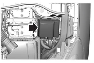
Head Up Display (HUD) combiner module
-
Head Up Display (HUD) combiner module
Remove the IPC .
Refer to: Instrument Panel Cluster (IPC) (413-01 Instrumentation, Message Center and Warning Chimes, Removal and Installation).
-
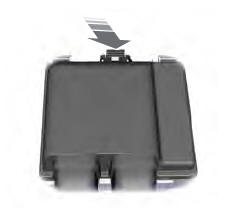
Remove the lower HUD combiner module bolt.
Torque: 33 lb.in (3.7 Nm)
.jpg) |
-
Remove the bolts and disconnect the HUD combiner electrical connector. Remove the HUD combiner module.
Torque: 33 lb.in (3.7 Nm)
.jpg) |
Installation
-
To install, reverse the removal procedure.
 Diagnosis and Testing - Collision Warning and Collision Avoidance System
Symptom Chart
Symptom Chart: Forward Collision Warning
Diagnostics in this manual assume a certain skill level and knowledge of Ford-specific diagnostic practices...

Other information:
Ford Escape 2020-2026 Service Manual: Removal and Installation - Hands-Free Liftgate Actuation Lower Sensor
Removal With the vehicle in NEUTRAL, position it on a hoist. Refer to: Jacking and Lifting (100-02) . Disconnect the hands-free liftgate actuation lower sensor electrical connector. Remove the push pins, the brackets and the lower hands-free liftgate sensor. Installation To install, reverse the removal proce..
Ford Escape 2020-2026 Owners Manual: Automatic Transmission
Automatic Transmission Precautions WARNING: When your vehicle is stationary, keep the brake pedal fully pressed when shifting gears. Failure to follow this instruction could result in personal injury, death or property damage. WARNING: Do not apply the brake pedal and accelerator pedal simultaneously. Applying both pedals simultaneously for more than a few seconds will limit power, which ..
Categories
- Manuals Home
- 4th Generation Ford Escape Owners Manual
- 4th Generation Ford Escape Service Manual
- Switching the Rear Window Wiper On and Off. Reverse Wipe
- Accessing the Trip Computer. Resetting the Trip Computer
- Locating the Pre-Collision Assist Sensors
- New on site
- Most important about car
Under Hood Fuse Box
Locating the Under Hood Fuse Box
Accessing the Under Hood Fuse Box
Copyright © 2026 www.fordescape4.com