Ford Escape: Rear Disc Brake / Removal and Installation - Brake Disc
Materials
| Name | Specification |
|---|---|
| Motorcraft® Metal Brake Parts Cleaner PM-4-A, PM-4-B, APM-4-C |
- |
Removal
 WARNING:
Service actions on vehicles equipped with electronic brake
booster and electronic parking brakes may cause unexpected brake
application, which could result in injury to hands or fingers. Put the
brake system into service mode prior to servicing or removing any brake
components. Failure to follow this instruction may result in serious
personal injury.
WARNING:
Service actions on vehicles equipped with electronic brake
booster and electronic parking brakes may cause unexpected brake
application, which could result in injury to hands or fingers. Put the
brake system into service mode prior to servicing or removing any brake
components. Failure to follow this instruction may result in serious
personal injury.
NOTE: Removal steps in this procedure may contain installation instructions.
-
Activate the brake service mode.
Refer to: Brake Service Mode Activation and Deactivation (206-00 Brake System - General Information, General Procedures).
-
Remove the wheel and tire.
Refer to: Wheel and Tire (204-04A Wheels and Tires, Removal and Installation).
-
NOTICE: Do not pry in the caliper sight hole to retract the pistons as this can damage the pistons and boots.
NOTICE: Do not allow the brake caliper and anchor plate assembly to hang from the brake hose or damage to the hose can occur.
Remove the bolts and position the brake caliper and anchor plate assembly aside. Discard the bolts.
Torque: 46 lb.ft (63 Nm)
 |
-
Remove the brake disc.
 |
-
NOTICE: Make sure that the mating faces are clean and free of foreign material.
Clean the brake disc-to-wheel hub mating surfaces.
Material: Motorcraft® Metal Brake Parts Cleaner / PM-4-A, PM-4-B, APM-4-C
 |
Installation
-
NOTICE: Make sure that the brake hose is not twisted when installing the brake caliper or damage to the brake flexible hose may occur.
To install, reverse the removal procedure.
-
Deactivate the brake service mode.
Refer to: Brake Service Mode Activation and Deactivation (206-00 Brake System - General Information, General Procedures).
-
Apply the brake pedal several times to verify correct brake system operation.
 Removal and Installation - Brake Caliper Anchor Plate
Materials
Name
Specification
Motorcraft® Metal Brake Parts CleanerPM-4-A, PM-4-B, APM-4-C
-
Removal
WARNING:
Service actions on vehicles equipped with electronic brake
booster and electronic parking brakes may cause unexpected brake
application, which could result in injury to hands or fingers...
 Removal and Installation - Brake Disc Shield
Removal
NOTE:
Removal steps in this procedure may contain installation details.
Remove the wheel hub and wheel bearing.
Refer to: Wheel Bearing and Wheel Hub - AWD (204-02 Rear Suspension, Removal and Installation)...
Other information:
Ford Escape 2020-2026 Service Manual: Removal and Installation - Head Up Display (HUD) Module
Special Tool(s) / General Equipment Interior Trim Remover Removal All vehicles NOTE: Removal steps in this procedure may contain installation details. Remove the HUD combiner module bezel. Use the General Equipment: Interior Trim Remover Head Up Display (HUD) combiner module screen Using a diagnostic scan tool, move the HUD combiner..
Ford Escape 2020-2026 Service Manual: Disassembly - Engine
Special Tool(s) / General Equipment 205-153 (T80T-4000-W) Handle 303-1247VCT Spark Plug Tube Seal Remover and InstallerTKIT-2006UF-FLMTKIT-2006UF-ROW 303-1416Tool, Crank Damper HoldingTKIT-2008ET-FLM 303-409 (T92C-6700-CH) Remover, Crankshaft SealTKIT-1992-FH/FMH/FLMHTKIT-1993-LMH/MH 303-465Tool, Camshaft Align TimingTKIT-1994-LMH/MH2TKIT-1994-FH/FMH/FLMH ..
Categories
- Manuals Home
- 4th Generation Ford Escape Owners Manual
- 4th Generation Ford Escape Service Manual
- Drive Modes
- Electric Parking Brake
- Plug-In Hybrid Electric Vehicle Drive Modes
- New on site
- Most important about car
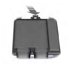
Under Hood Fuse Box
Locating the Under Hood Fuse Box
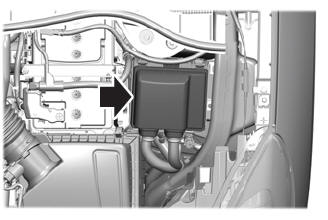
Accessing the Under Hood Fuse Box