Ford Escape 2020-2026 Service Manual / Powertrain / Engine / Electronic Engine Controls / Diagnosis and Testing - Crankshaft Position System
Ford Escape: Electronic Engine Controls / Diagnosis and Testing - Crankshaft Position System
Diagnostic Trouble Code (DTC) Chart
Diagnostics in this manual assume a certain skill level and knowledge of Ford-specific diagnostic practices.
REFER to: Diagnostic Methods (100-00 General Information, Description and Operation).
| Module | DTC | Description | Action |
|---|---|---|---|
| PCM | P0315:00 | Crankshaft Position System Variation Not Learned: No Sub Type Information | GO to Pinpoint Test JD |
| PCM | P0335:00 | Crankshaft Position Sensor 'A' Circuit: No Sub Type Information | GO to Pinpoint Test JD |
| PCM | P0339:00 | Crankshaft Position Sensor 'A' Circuit Intermittent: No Sub Type Information | GO to Pinpoint Test JD |
| PCM | P033F:00 | Crankshaft/Camshaft Loss Of Synchronization: No Sub Type Information | GO to Pinpoint Test JD |
| PCM | P1336:00 | Crankshaft/Camshaft Sensor Range/Performance: No Sub Type Information | GO to Pinpoint Test JD |
| PCM | P2617:00 | Crankshaft Position Output Circuit/Open: No Sub Type Information | GO to Pinpoint Test JD |
Global Customer Symptom Code (GCSC) Chart
Diagnostics in this manual assume a certain skill level and knowledge of Ford-specific diagnostic practices.
REFER to: Diagnostic Methods (100-00 General Information, Description and Operation).
| Symptom | Action |
|---|---|
| Start/Run/Move > Starting > Hard Start/Long Crank > Always | GO to Pinpoint Test JD |
Pinpoint Tests
 PINPOINT TEST JD: CRANKSHAFT POSITION (CKP) SENSOR
.jpg)
.png) Introduction Introduction
Normal Operation and Fault Conditions Refer to the DTC Fault Trigger Conditions. DTC Fault Trigger Conditions
Possible Sources
|
 Description and Operation - Electronic Engine Controls - System Operation and Component Description
System Operation
Comprehensive Component Monitor (CCM)
The
comprehensive component monitor (CCM) checks for concerns in any
powertrain electronic component or circuit that provides input or output
signals to the PCM that can affect emissions and is not monitored by another OBD
monitor...
 Diagnosis and Testing - Electronic Engine Controls
Diagnostic Trouble Code (DTC) Chart
Diagnostics in this manual assume a certain skill level and knowledge of Ford-specific diagnostic practices. REFER to: Diagnostic Methods (100-00 General Information, Description and Operation)...
Other information:
Ford Escape 2020-2026 Owners Manual: Traction Control
How Does Traction Control Work If your vehicle begins to slide, the system applies the brakes to individual wheels and, when needed, reduces power at the same time. If the wheels spin when accelerating on slippery or loose surfaces, the system reduces power in order to increase traction...
Ford Escape 2020-2026 Owners Manual: Heated Seats
(If Equipped) Heated Seat Precautions WARNING: Use caution when using the heated seat if you are unable to feel pain to your skin because of advanced age, chronic illness, diabetes, spinal cord injury, medication, alcohol use, exhaustion or other physical conditions...
Categories
- Manuals Home
- 4th Generation Ford Escape Owners Manual
- 4th Generation Ford Escape Service Manual
- All-Wheel Drive
- Description and Operation - Identification Codes
- Switching the Rear Window Wiper On and Off. Reverse Wipe
- New on site
- Most important about car
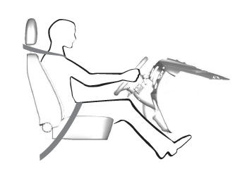
Sitting in the Correct Position

When you use them properly, the seat, head restraint, seatbelt and airbags will provide optimum protection in the event of a crash.
Copyright © 2026 www.fordescape4.com

 PINPOINT TEST JD: CRANKSHAFT POSITION (CKP) SENSOR

 Introduction