
Ford Escape 2020-2026 Service Manual / Powertrain / Engine / Starting System - 1.5L EcoBoost (132kW/180PS) – I3 (Y1)
Ford Escape: Engine / Starting System - 1.5L EcoBoost (132kW/180PS) – I3 (Y1)
- Specifications
- Description and Operation - Starting System - Overview
- Description and Operation - Starting System - System Operation and Component Description
- Diagnosis and Testing - Starting System
- General Procedures - Starter Amperage Draw Test
- General Procedures - Starter Motor Drive Gear and Flywheel Ring Gear Inspection
- Removal and Installation - Starter Motor
 Removal and Installation - Accessory Drive Belt Tensioner
Removal
NOTICE:
Under no circumstances should the accessory drive belt,
tensioner or pulleys be lubricated as potential damage to the belt
material and tensioner damping mechanism will occur...
 Specifications
General Specifications
Item
Specification
Normal engine cranking speed (Average)
200-300 Revolutions Per Minute (RPM)
Starting circuit maximum voltage drop (Engine at normal operating temperature) (Average)
0...
Other information:
Ford Escape 2020-2026 Service Manual: Description and Operation - Perimeter Anti-Theft Alarm - System Operation and Component Description
System Operation System Diagram Item Description 1 Power Liftgate 2 Hood Ajar Switch 3 Passive Key 4 Horn 5 GWM 6 GWM 7 PDM 8 DLC 9 IPC 10 RTM 11 BCM 12 Left Door Lock Control Switch 13 DDM 14 Right Door Lock Control Switch 15 Ignition Switch 1..
Ford Escape 2020-2026 Service Manual: Removal and Installation - Audio Digital Signal Processing (DSP) Module
Removal NOTE: Removal steps in this procedure may contain installation details. NOTE: If installing a new module, it is necessary to upload the module configuration information to the scan tool prior to removing the module. This information must be downloaded into the new module after installation. Using a diagnostic scan tool, begin the PMI process for the DSP following the on..
Categories
- Manuals Home
- 4th Generation Ford Escape Owners Manual
- 4th Generation Ford Escape Service Manual
- Adjusting the Headlamps
- Accessing the Trip Computer. Resetting the Trip Computer
- Symbols Glossary
- New on site
- Most important about car
Under Hood Fuse Box
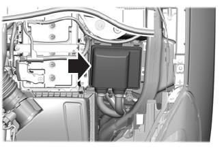
Locating the Under Hood Fuse Box
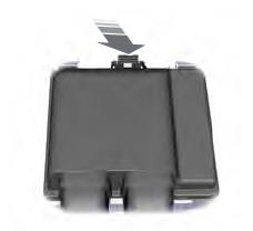
Accessing the Under Hood Fuse Box

Copyright © 2026 www.fordescape4.com