Ford Escape 2020-2025 Service Manual / Body and Paint / Frame and Mounting / Uni-Body, Subframe and Mounting System / Removal and Installation - Rear Subframe Front Bushing
Ford Escape: Uni-Body, Subframe and Mounting System / Removal and Installation - Rear Subframe Front Bushing
Special Tool(s) / General Equipment
.jpg) |
204-598 Hydraulic Cylinder 10t |
.jpg) |
204-598-01 Remover/Installer, Subframe Bushing Guide |
.jpg) |
204-598-04 Adapter for 204-598 |
.jpg) |
204-598-05 Adapter for 204-598 |
Removal
NOTE: Removal steps in this procedure may contain installation details.
-
Remove the rear subframe.
Refer to: Rear Subframe (502-00) .
-
NOTE: Note the position of the components before removal.
Index-mark the subframe bushing location to aid in installation.
.jpg) |
-
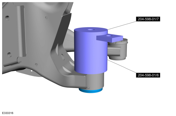
Assemble the subframe bushing guide to the rear subframe.
Use Special Service Tool: 204-598-01 Remover/Installer, Subframe Bushing Guide.
 |
-
Assemble the special service tool.
Use Special Service Tool: 204-598-01 Remover/Installer, Subframe Bushing Guide.
.jpg) |
-
Assemble the adapter.
Use Special Service Tool: 204-598-05 Adapter for 204-598.
.jpg) |
-
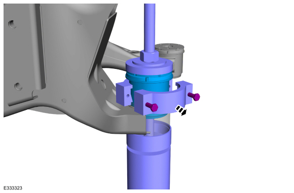
Assemble the special tools and remove the rear subframe front bushing.
Use Special Service Tool: 204-598 Hydraulic Cylinder 10t. , 204-598-01 Remover/Installer, Subframe Bushing Guide.
.jpg) |
Installation
-
NOTICE: Make sure that the component aligns with the installation mark.
Assemble the special tools to the rear subframe with the new subframe bushing.
Use Special Service Tool: 204-598-04 Adapter for 204-598. , 204-598-01 Remover/Installer, Subframe Bushing Guide.
.jpg) |
-
Press the new subframe bushing into the rear subframe.
Use Special Service Tool: 204-598 Hydraulic Cylinder 10t. , 204-598-04 Adapter for 204-598. , 204-598-01 Remover/Installer, Subframe Bushing Guide.
.jpg) |
.jpg) |
-
Remove the adapter.
 |
-
Install the rear subframe bushing and remove the special tools.
 |
-
Install the rear subframe.
Refer to: Rear Subframe (502-00) .
 Removal and Installation - Rear Subframe
Special Tool(s) /
General Equipment
300-OTC1585AEPowertrain Lift
Wooden Block
Removal
NOTICE:
Suspension fasteners are critical parts that affect the
performance of vital components and systems...
 Removal and Installation - Rear Subframe Rear Bushing
Special Tool(s) /
General Equipment
204-598Hydraulic Cylinder 10t
204-598-01Remover/Installer, Subframe Bushing Guide
204-598-04Adapter for 204-598
Removal
Remove the rear subframe...
Other information:
Ford Escape 2020-2025 Service Manual: Removal and Installation - Driver Front Seat Module (DSM)
Removal NOTE: This step is only necessary when installing a new component. NOTE: The PMI (programmable module installation) process must begin with the current DSM (driver front seat module) installed. If the current DSM (driver front seat module) does not respond to the diagnostic scan tool, the tool may prompt for As-Built Data as part of the repair...
Ford Escape 2020-2025 Owners Manual: SYNC Mobile Apps
The system enables voice and steering wheel control of SYNC AppLink enabled smartphone apps. When an app is running through AppLink, you can control main features of the app through voice commands and steering wheel controls. Note: You must pair and connect your smartphone to SYNC to access AppLink...
Categories
- Manuals Home
- 4th Generation Ford Escape Owners Manual
- 4th Generation Ford Escape Service Manual
- Rear View Camera
- Electric Parking Brake
- All-Wheel Drive
- New on site
- Most important about car
Fastening the Seatbelts

Copyright © 2025 www.fordescape4.com
