Ford Escape 2020-2025 Service Manual / Electrical / Instrumentation and Warning Systems / Instrumentation, Message Center and Warning Chimes / Removal and Installation - Instrument Panel Cluster (IPC)
Ford Escape: Instrumentation, Message Center and Warning Chimes / Removal and Installation - Instrument Panel Cluster (IPC)
Special Tool(s) / General Equipment
| Interior Trim Remover |
Removal
NOTE: Removal steps in this procedure may contain installation details.
-
NOTE: If installing a new module, it is necessary to upload the module configuration information to the scan tool prior to removing the module. This information must be downloaded into the new module after installation.
Using a diagnostic scan tool, begin the PMI process for the IPC following the on-screen instructions. Record the odometer value from the original IPC . If the odometer value cannot be obtained from the IPC (display failure), perform the diagnostic routine. If the value cannot be obtained after the diagnostic routine, the customer should supply the approximate odometer value.
-
Position the steering wheel to the full downward and outward postion.
.jpg) |
-
Remove the information and entertainment display unit.
Refer to: Center Display Screen (415-00 Information and Entertainment System - General Information, Removal and Installation).
-
Remove the screws.
Torque: 22 lb.in (2.5 Nm)
.jpg) |
-
NOTE: Make sure that new retaining clips are installed.
Remove and discard the retaining clips. Disconnect the electrical connector and remove the center stack trim.
Use the General Equipment: Interior Trim Remover
.jpg) |
-
Unclip the gap hider from the upper steering column shroud and instrument cluster rim.
Use the General Equipment: Interior Trim Remover
.jpg) |
-
-
Remove the bolt.
Torque: 22 lb.in (2.5 Nm)
-
Remove the bolts.
Torque: 33 lb.in (3.7 Nm)
-
Release the clips and remove the instrument cluster bezel.
Use the General Equipment: Interior Trim Remover
-
Remove the bolt.
.jpg) |
-
-
Remove the screws.
Torque: 22 lb.in (2.5 Nm)
-
Disconnect the electrical connector and remove the IPC .
-
Remove the screws.
.jpg) |
Installation
-
To install, reverse the removal procedure.
-
Using a diagnostic scan tool, complete the PMI process for the IPC following the on-screen instructions.
 General Procedures - Seatbelt Minder Deactivating/Activating
Activation
WARNING:
Before beginning any service procedure in this section,
refer to Safety Warnings in section 100-00 General Information...
 Removal and Installation - Instrument Panel Cluster (IPC) Lens
Removal
Remove the IPC .
Refer to: Instrument Panel Cluster (IPC) (413-01 Instrumentation, Message Center and Warning Chimes, Removal and Installation)...
Other information:
Ford Escape 2020-2025 Service Manual: Removal and Installation - Front Door Latch
Removal NOTE: LH (left-hand) side shown, RH (right-hand) side similar. NOTE: Removal steps in this procedure may contain installation details. Remove the front door window regulator and motor. Refer to: Front Door Window Regulator and Motor (501-11 Glass, Frames and Mechanisms, Removal and Installation)...
Ford Escape 2020-2025 Service Manual: Removal and Installation - Manifold Absolute Pressure and Temperature (MAPT) Sensor
Removal NOTE: Removal steps in this procedure may contain installation details. Disconnect the electrical connector, remove the retainer and the MAP sensor. Torque: 35 lb.in (4 Nm) Installation To install, reverse the removal procedure...
Categories
- Manuals Home
- 4th Generation Ford Escape Owners Manual
- 4th Generation Ford Escape Service Manual
- Adjusting the Headlamps
- Fuel Quality
- Traction Control
- New on site
- Most important about car
Under Hood Fuse Box
Locating the Under Hood Fuse Box
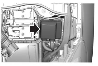
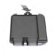
Accessing the Under Hood Fuse Box
Copyright © 2025 www.fordescape4.com