Ford Escape: Supplemental Restraint System / Removal and Installation - C-Pillar Side Impact Sensor
Removal
 WARNING:
The following procedure prescribes critical repair steps
required for correct restraint system operation during a crash. Follow
all notes and steps carefully. Failure to follow step instructions may
result in incorrect operation of the restraint system and increases the
risk of serious personal injury or death in a crash.
WARNING:
The following procedure prescribes critical repair steps
required for correct restraint system operation during a crash. Follow
all notes and steps carefully. Failure to follow step instructions may
result in incorrect operation of the restraint system and increases the
risk of serious personal injury or death in a crash.
NOTE: LH (left-hand) shown, RH (right-hand) similar.
NOTE: Removal steps in this procedure may contain installation details.
-
Refer to: Pyrotechnic Device Health and Safety Precautions (100-00 General Information, Description and Operation).
WARNING:
Before beginning any service procedure in this
manual, refer to health and safety warnings in section 100-00 General
Information. Failure to follow this instruction may result in serious
personal injury.
-
Depower the SRS .
Refer to: Supplemental Restraint System (SRS) Depowering (501-20B Supplemental Restraint System, General Procedures).
-
Remove the rear scuff plate trim panel.
Refer to: Rear Scuff Plate Trim Panel (501-05 Interior Trim and Ornamentation, Removal and Installation).
-
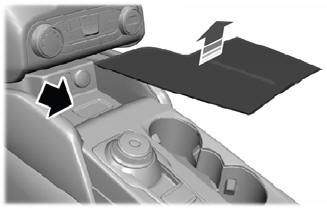
Position the weather-strip away from the C-pillar trim panel.
.jpg) |
-
NOTE: Second row seat removed for clarity.
Release the clips and position the loadspace trim panel away enough to access the C-pillar side impact sensor.
.jpg) |
-
-
Disconnect the C-pillar side impact sensor electrical connector.
-
Remove the C-pillar side impact sensor bolt.
Torque: 93 lb.in (10.5 Nm)
-
Remove the C-pillar side impact sensor.
-
Disconnect the C-pillar side impact sensor electrical connector.
.jpg) |
Installation
-
NOTE: The C-pillar side impact sensor mating surfaces must be smooth and allow for a flush attachment to each other.
To install, reverse the removal procedure.
-
Repower the SRS .
Refer to: Supplemental Restraint System (SRS) Repowering (501-20B Supplemental Restraint System, General Procedures).
 Removal and Installation - Battery Energy Control Module B (BECMB)
Removal
WARNING:
The following procedure prescribes critical repair steps
required for correct restraint system operation during a crash. Follow
all notes and steps carefully...
 Removal and Installation - Clockspring
Removal
WARNING:
The following procedure prescribes critical repair steps
required for correct restraint system operation during a crash. Follow
all notes and steps carefully...
Other information:
Ford Escape 2020-2025 Owners Manual: General Information
WARNING: Driving while distracted can result in loss of vehicle control, crash and injury. We strongly recommend that you use extreme caution when using any device that may take your focus off the road. Your primary responsibility is the safe operation of your vehicle...
Ford Escape 2020-2025 Service Manual: Removal and Installation - Hood Latch Release Handle
Removal Remove the hood latch release handle. Rotate the hood latch release handle. NOTE: Do not remove the retaining clip from the hood latch release handle. Release the retaining clip. Remove the hood latch release handle...
Categories
- Manuals Home
- 4th Generation Ford Escape Owners Manual
- 4th Generation Ford Escape Service Manual
- Traction Control
- Opening and Closing the Hood
- General Procedures - Brake Service Mode Activation and Deactivation
- New on site
- Most important about car
Master Access Code
What Is the Master Access Code
The master access code is a factory-set five-digit entry code. You can operate the keypad with the master access code at any time. The master access code is on the owner’s wallet card in the glove box and is available from an authorized dealer.
Displaying the Master Access Code
To display the factory-set code in the information display: