Ford Escape 2020-2025 Service Manual / Electrical / Climate Control System / Climate Control System - General Information / Removal and Installation - Air Distribution Door Actuator
Ford Escape: Climate Control System - General Information / Removal and Installation - Air Distribution Door Actuator
Removal
-
Remove the glove compartment.
Refer to: Glove Compartment (501-12 Instrument Panel and Console, Removal and Installation).
-
Remove the screws and the air distribution door actuator.
-
Disconnect the electrrical connector.
-
Disconnect the electrrical connector.
.jpg) |
Installation
-
To install, reverse the removal procedure.
-
Using a diagnostic scan tool, carry out the Climate
Control System Actuator Calibration following the on-screen
instructions.
 Removal and Installation - Air Conditioning (A/C) Pressure Transducer - 1.5L EcoBoost (132kW/180PS) – I3 (Y1)
Removal
NOTE:
Removal steps in this procedure may contain installation details.
Disconnect the electrical connector and remove the A/C pressure transducer...
 Removal and Installation - Air Inlet Door Actuator
Removal
Remove the climate control housing.
Refer to: Climate Control Housing (412-00 Climate Control System - General Information, Removal and Installation)...
Other information:
Ford Escape 2020-2025 Owners Manual: Electromagnetic Compatibility
WARNING: Do not place objects or mount equipment on or near the airbag cover, on the side of the front or rear seatbacks, or in areas that may come into contact with a deploying airbag. Failure to follow these instructions may increase the risk of personal injury in the event of a crash...
Ford Escape 2020-2025 Service Manual: Removal and Installation - Hazard Flasher Switch
Removal NOTE: Removal steps in this procedure may contain installation details. Remove the center registers. Refer to: Center Registers (412-00 Climate Control System - General Information, Removal and Installation). Release the tabs and remove the hazard flasher switch from the center registers...
Categories
- Manuals Home
- 4th Generation Ford Escape Owners Manual
- 4th Generation Ford Escape Service Manual
- Fuel Quality
- Locating the Pre-Collision Assist Sensors
- What Is the Tire Pressure Monitoring System. Tire Pressure Monitoring System Overview
- New on site
- Most important about car
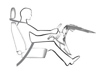
Sitting in the Correct Position

When you use them properly, the seat, head restraint, seatbelt and airbags will provide optimum protection in the event of a crash.
Copyright © 2025 www.fordescape4.com
