
Ford Escape: Driveline / Driveshaft
- Specifications
- Diagnosis and Testing - Driveshaft
- General Procedures - Driveshaft Angle Measurement
- General Procedures - Driveshaft Runout and Balancing
- Removal and Installation - Rear Driveshaft
 Driveline
..
 Specifications
Item
1.5L EcoBoost
2.0L EcoBoost
2.5L Duratec HEV
Driveshaft runout
0.6 mm (0.024 in)
0...
Other information:
Ford Escape 2020-2026 Service Manual: Description and Operation - Glass, Frames and Mechanisms - Vehicles With: One-Touch Open Driver Window - System Operation and Component Description
System Operation System Diagram - Rear Window Defrost Item Description 1 BJB 2 HVAC Module 3 MS-CAN 4 Rear Window Defrost Grid 5 GWM 6 BCM 7 HS-CAN1 8 LIN Network Message Chart - Rear Window Defrost BCMC Network Input Messages Broadcast Messa..
Ford Escape 2020-2026 Service Manual: Diagnosis and Testing - High Voltage Battery, Mounting and Cables - Hybrid Electric Vehicle (HEV)
Diagnostic Trouble Code (DTC) Chart Diagnostics in this manual assume a certain skill level and knowledge of Ford-specific diagnostic practices. REFER to: Diagnostic Methods (100-00 General Information, Description and Operation). WARNING: To prevent the risk of high-voltage shock, always follow precisely all warnings and service instructions, including instructions to depower the..
Categories
- Manuals Home
- 4th Generation Ford Escape Owners Manual
- 4th Generation Ford Escape Service Manual
- Opening and Closing the Hood
- Accessing the Trip Computer. Resetting the Trip Computer
- Adjusting the Headlamps
- New on site
- Most important about car
Sitting in the Correct Position
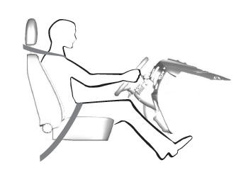
When you use them properly, the seat, head restraint, seatbelt and airbags will provide optimum protection in the event of a crash.

Copyright © 2026 www.fordescape4.com