Ford Escape 2020-2026 Service Manual / Chassis / Steering System / Steering Wheel and Column Electrical Components / Removal and Installation - Steering Column Control Module (SCCM)
Ford Escape: Steering Wheel and Column Electrical Components / Removal and Installation - Steering Column Control Module (SCCM)
Removal
NOTE: Removal steps in this procedure may contain installation details.
-
NOTE: This step is only necessary when installing a new component.
NOTE: The PMI process must begin with the current SCCM installed. If the current SCCM does not respond to the diagnostic scan tool, the tool may prompt for As-Built Data as part of the repair.
Using a diagnostic scan tool, begin the PMI process for the SCCM following the on-screen instructions.
-
Remove the steering wheel.
Refer to: Steering Wheel (211-04 Steering Column, Removal and Installation).
-
Remove the steering column shrouds.
Refer to: Steering Column Shrouds (501-05 Interior Trim and Ornamentation, Removal and Installation).
-
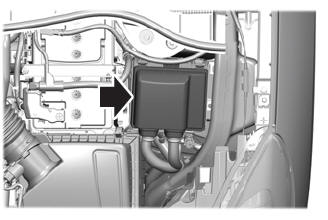
Disconnect the SCCM electrical connectors and position the wiring harness aside.
 |
-
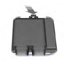
Remove the retainers and the SCCM .
Torque: 27 lb.in (3 Nm)
 |
Installation
-
To install, reverse the removal procedure.
-
NOTE: This step is only necessary when installing a new component.
Using a diagnostic scan tool, complete the PMI process for the SCCM following the on-screen instructions.
 Diagnosis and Testing - Steering Wheel and Column Electrical Components
Diagnostic Trouble Code (DTC) Chart
Diagnostics in this manual assume a certain skill level and knowledge of Ford-specific diagnostic practices. REFER to: Diagnostic Methods (100-00 General Information, Description and Operation)...
 Removal and Installation - Ignition Lock Cylinder Housing
Removal
Remove the SCCM .
Refer to: Steering Column Control Module (SCCM) (211-05 Steering Wheel
and Column Electrical Components, Removal and Installation)...
Other information:
Ford Escape 2020-2026 Service Manual: Description and Operation - Instrument Panel and Interior Switches Illumination - System Operation and Component Description
System Operation System Diagram - Networked Illumination Item Description 1 APIM 2 Light Sensor 3 ACM 4 IPC 5 DDM 6 PDM 7 BCM 8 RF Door Lock Switch 9 RF Door Window Control Switch 10 LF Door Window Control Switch 11 RR Door Window Control Switch 12 LR Door Window Con..
Ford Escape 2020-2026 Owners Manual: Engine Oil Capacity and Specification - 1.5L EcoBoost™
Use oil that meets the defined specification and viscosity grade. If you do not use oil that meets the defined specification and viscosity grade, it could result in: Component damage that your vehicle warranty does not cover. Longer engine cranking periods. Increased emission levels. Reduced vehicle performance. Reduced fuel economy. An oil that displays this symbol conforms to curre..
Categories
- Manuals Home
- 4th Generation Ford Escape Owners Manual
- 4th Generation Ford Escape Service Manual
- Locating the Pre-Collision Assist Sensors
- Opening and Closing the Hood
- Fuel Quality
- New on site
- Most important about car
Under Hood Fuse Box
Locating the Under Hood Fuse Box
Accessing the Under Hood Fuse Box
Copyright © 2026 www.fordescape4.com