Ford Escape: Engine Ignition / Removal and Installation - Ignition Coil-On-Plug
Removal
.jpg) WARNING:
Before beginning any service procedure in this section,
refer to Safety Warnings in section 100-00 General Information. Failure
to follow this instruction may result in serious personal injury.
WARNING:
Before beginning any service procedure in this section,
refer to Safety Warnings in section 100-00 General Information. Failure
to follow this instruction may result in serious personal injury.
NOTE: Removal steps in this procedure may contain installation details.
-
Refer to: Health and Safety Precautions (100-00 General Information, Description and Operation).
-
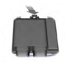
NOTICE: Do not pull the engine appearance cover forward or sideways to remove. Failure to press straight upward on the underside of the cover at the attachment points may result in damage to the cover or engine components.
NOTE: Lubricating the grommets with silicone grease will aid in the installation of the engine appearance cover, and any future removal and installation of the cover.
-
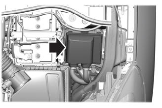
Remove the stud.
Torque: 35 lb.in (4 Nm)
-
Remove the engine appearance cover.
-
Remove the stud.
.jpg) |
-
NOTE: Use compressed air to remove any foreign material from the ignition coil-on-plugs and surrounding area before removing the ignition coil-on-plugs.
NOTE: When removing the ignition coil-on-plugs, a slight twisting motion will break the seal and ease removal.
-
NOTE: If equipped with a sliding cover over the locking tab, then slide the cover back to gain access to the tab.
Depress the locking tab on the ignition coil-on-plug electrical connector, and disconnect the electrical connector from the ignition coil-on-plug.
-
Remove the ignition coil-on-plug retainers.
Torque: 71 lb.in (8 Nm)
-
Remove the ignition coil-on-plugs.
-
 |
-
Inspect the ignition coil-on-plug assemblies for cracks,
rips, or tears and replace any damaged coil-on-plug assemblies.
.jpg) |
Installation
-
To install, reverse the removal procedure.
 Diagnosis and Testing - Engine Ignition
Diagnostic Trouble Code (DTC) Chart
Diagnostics in this manual assume a certain skill level and knowledge of Ford-specific diagnostic practices. REFER to: Diagnostic Methods (100-00 General Information, Description and Operation)...
 Removal and Installation - Spark Plugs
Removal
WARNING:
Before beginning any service procedure in this section,
refer to Safety Warnings in section 100-00 General Information. Failure
to follow this instruction may result in serious personal injury...
Other information:
Ford Escape 2020-2025 Service Manual: Diagnosis and Testing - Direct Current/Alternating Current (DC/AC) Inverter
Inspection and Verification Before diagnosing or repairing the Direct Current/Alternating Current (DC/AC) Inverter system refer to the Owner's Literature and REFER to: Direct Current/Alternating Current (DC/AC) Inverter - System Operation and Component Description (414-05 Voltage Converter/Inverter, Description and Operation)...
Ford Escape 2020-2025 Service Manual: Removal and Installation - Passenger Door Module (PDM)
Removal NOTE: Removal steps in this procedure may contain installation details. NOTE: Drivers side shown, passenger side similar. NOTE: If installing a new module, it is necessary to upload the module configuration information to the diagnostic scan tool prior to removing the module...
Categories
- Manuals Home
- 4th Generation Ford Escape Owners Manual
- 4th Generation Ford Escape Service Manual
- Description and Operation - Identification Codes
- Child Safety Locks
- Symbols Glossary
- New on site
- Most important about car
Under Hood Fuse Box
Locating the Under Hood Fuse Box
Accessing the Under Hood Fuse Box