Ford Escape 2020-2026 Service Manual / Body and Paint / Body and Paint / Body Closures / Removal and Installation - Hands-Free Liftgate Actuation Module
Ford Escape: Body Closures / Removal and Installation - Hands-Free Liftgate Actuation Module
Removal
-
With the vehicle in NEUTRAL, position it on a hoist.
Refer to: Jacking and Lifting - Overview (100-02 Jacking and Lifting, Description and Operation).
-
Disconnect the hands-free liftgate actuation module electrical connectors.
.jpg) |
-
-
Disconnect the hands-free liftgate actuation module electrical connector.
-
Remove the fasteners and hands free liftgate actuation module.
-
Disconnect the hands-free liftgate actuation module electrical connector.
.jpg) |
Installation
-
To install, reverse the removal procedure.
-
NOTE: This step is only necessary when installing a new component.
Using a diagnostic scan tool, perform a LIN new module initialization following the on-screen instructions.
 Removal and Installation - Hands-Free Liftgate Actuation Lower Sensor
Removal
With the vehicle in NEUTRAL, position it on a hoist.
Refer to: Jacking and Lifting (100-02)
.
Disconnect the hands-free liftgate actuation lower sensor electrical connector...
 Removal and Installation - Hands-Free Liftgate Actuation Upper Sensor
Removal
With the vehicle in NEUTRAL, position it on a hoist.
Refer to: Jacking and Lifting (100-02)
.
Drill the rivets, release the tabs and remove the lower rear bumper cover valence
Disconnect the hands-free liftgate actuation upper sensor electrical connector...
Other information:
Ford Escape 2020-2026 Service Manual: Description and Operation - Parking Aid - System Operation and Component Description
System Operation Active Park Assist System Diagram Item Description 1 Rear door speakers 2 Front door speakers 3 Audio system display 4 TRM 5 BCM 6 PCM 7 ABS module 8 DSP 9 ACM 10 IPC 11 APIM 12 PSCM 13 with 10 speaker system 14 GWM 15 S..
Ford Escape 2020-2026 Owners Manual: Operating the Doors From Inside Your Vehicle
Unlocking and Locking the Doors Using the Central Locking The power door lock control is on the driver door. Press the button to unlock all doors. Press the button to lock all doors. Individually Unlocking and Locking the Doors Using the Locking Button The power door lock control is on the driver and front passenger door panels. Unlock. Lock. ..
Categories
- Manuals Home
- 4th Generation Ford Escape Owners Manual
- 4th Generation Ford Escape Service Manual
- Accessing the Trip Computer. Resetting the Trip Computer
- Switching the Rear Window Wiper On and Off. Reverse Wipe
- Drive Modes
- New on site
- Most important about car
Sitting in the Correct Position
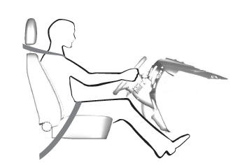
When you use them properly, the seat, head restraint, seatbelt and airbags will provide optimum protection in the event of a crash.
Copyright © 2026 www.fordescape4.com