Ford Escape: Bumpers / Disassembly and Assembly - Front Bumper Cover
Special Tool(s) /
General Equipment
DISASSEMBLY
-
Remove the front bumper cover.
Refer to: Front Bumper Cover (501-19 Bumpers, Removal and Installation).
-
On both sides.
Remove the screws, release the tabs and remove the stone deflector.
Torque:
18 lb.in (2 Nm)
-
-
Disconnect the fog lamp electrical connectors.
-
Disconnect the front parking aid sensor electrical connectors.
-
Disconnect the front active park assist sensor electrical connectors.
-
Disconnect the ambient air temperature sensor electrical connector.
-
Separate the harness guides, harness retainers and remove the front bumper cover harness.
-
If equipped, on both sides.
Remove the screws and the foglamp assembly.
-
On both sides.
Remove the screws and fog lamp bezel.
-
NOTE:
Make sure that the isolator rings are installed correctly while installing the sensors.
If equipped.
Remove the front parking aid sensors and front active park assist sensors.
-
Release the tabs.
-
Remove the front parking aid sensors and front active park assist sensors from the bracket.
-
Detach and remove the ambient air temperature sensor.
-
Release the tabs and remove the front bumper cover reinforcement.
-
Release the trim pins and remove the hood seal.
-
Release the tabs and remove the front bumper cover reinforcement mounting bracket.
-
If equipped.
Drill the rivets and remove the license plate bracket.
-
Remove the screws and the radiator close out panel.
-
Remove the push pins, release the tabs and remove the front bumper cover protector.
-
Release the tabs and remove the radiator grille.
-
Drill the rivets, release the tabs and remove the lower bumper cover panel.
-
Remove the push nuts and the front bumper cover emblem.
Use the General Equipment: Hot Air Gun
-
On both sides.
Drill the rivets and remove the front bumper cover to fender bracket.
ASSEMBLY
-
To assemble, reverse the disassembly procedure.
-
Adjust the fog lamp.
Refer to: Front Fog Lamp Adjustment (417-01 Exterior Lighting, General Procedures).
Special Tool(s) /
General Equipment
Interior Trim Remover
Removal
NOTE:
Removal steps in this procedure may contain installation details...
DISASSEMBLY
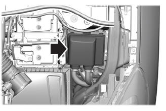
Remove the rear bumper cover.
Refer to: Rear Bumper Cover (501-19 Bumpers, Removal and Installation).
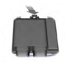
Disconnect the hands-free liftgate module electrical connector...
Other information:
System Operation
System Diagram
E358047
*.sttxt {
visibility: hidden;
}
*.stcallout {
visibility: visible;
}
1
PCM
2
ABS
3
SOBDMC
4
Active Grille
Shutter Actuator
Item
Description
1
PCM
2
ABS
3
SOBDMC
4
Act..
Removal
Remove the wiper linkage assembly.
Refer to: Wiper Linkage Assembly (501-16 Wipers and Washers, Removal and Installation).
Detach the windshield wiper link from the windshield wiper motor crank and position aside.
NOTE:
Note the position of the component before moving.
Rotate the windshield wiper motor crank to gain access to a..
.jpg)
.jpg)
.jpg)
.jpg)
.jpg)
.jpg)
.jpg)
.jpg)
.jpg)

.jpg)
.jpg)
.jpg)
.jpg)
.jpg)
.jpg)
.jpg)
 Removal and Installation - Rear Bumper Cover
 Disassembly and Assembly - Rear Bumper Cover